This Blog is now closed, please follow the link below
R2D2 Computer Case Mod
Saturday, 25 September 2010
Sunday, 7 February 2010
R6: End of a mad weekend

Battery box roughed together. I will finish it of properly later or, for now it is functional.
Themoulding has been added to the rear of the main feet to hide the motor brackets. It is hard to see from the photos but on the whole it looks fine.One other thing that I did have to re-shape was the skirt. For some reason I got the side pannels wrong. The angle was to steep, somehow I managed to get this wrong but it only became apparent when everything was fitted together on the test run. Anyway, old ones taken of and new ones fitted at the correct angle.
Movement at last

After all the messing around with getting everything to fit together correctly, atlast it all works. The feet now stay locked in position and do not tip and I have correct radio control. Even at 12v the motors are more than powerful enough on a noral road surface. I will get a video loaded soon showing the movement. Battery life seems ok , In the twenty mins I drove the droid around nothing fell off or broke.Even after hitting a wall at low speed the front foot survived, I am glad I reinforced it with MDF and metal strips.
The last image show how it has all been stripped down and re painted and the work done on the back of the main feet to cover the motor bracket hole.
Hopefully I will soon be ready for top coat painting. I still have not decided if I will spend laods of money on spray paints or go for the hand painted approach?
R6: Time for the basic Motor electrics

I started on the motor electrics board tonight. Each electrical system will have its own dedicated board making it easier to work on a dn upgrade when needed.
The main motor board has the Sabretooth dual25A speed control, reciever, fusebox, switches and multiblock fitted. Each motor and main battery is protected by fuses, 20 and 25A seems to do the trick. One set of multi blocks allows the motor connection and the other the batteries, either 24v or 12v config.
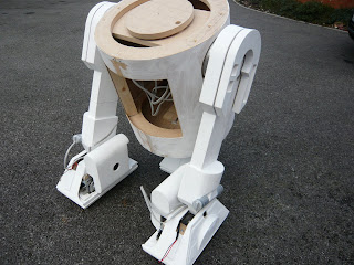
I decided to assemble the droid and test all the motors and electrics. After an hour or two fitting the feet to the legs and getting them onto the body I was ready to see if I had power and control. This was the point that everything went wrong. Here is the list of all the thing that failed:
The front foot kept tipping.
The main feet kept tipping
The battery boxes are not straight and the gap between the ankle and battery box is to large
The radio does not control the motors correctly.
24v is a joke unless I want a droid that can wheelie
After a depressing couple of hours of removing the battery boxes and getting a better fit I started work on the center foot. The problem is that I can not tighten up the bolts enough to stop the feet tipping. The solution has to be small wood blocks placed accordingly to stop the feet tipping, and heavier bushes placed on the pivots of each foot. You can see in the pictures that the small blocks are not really that noticable.
As for the control or lack of it I eventually found the problem. Working for hours in a cold garage does not help with diagnosing wiring faults. Can you spot the stupid wiring mistake on the board above. It took me two hours to find it. Now everthing drives perfectly.
R6: Fittings

More work on details. Shoulder hubs sanded and covered in alluminium tape. It gives a great look and makes the units look like they are cut from solid alloy when fitted. The ankle details ahve been re-sanded and ready for the top coat of paint. The wood ankle brackets have been binned and replace with 3mm alloy , which should look much better. Braided hose also puchased and ready to bronze.
R6: Legs and Feet coming together now
The drive untis are now fixed into the foot shells and the centre foot assembled. You can see from the pictures the problem I have with the rear of the outside feet and the way the motor backet sticks out. If I had better metal working skills I would have made up new metal brackets and solved this problem very quickly however I do not so it is going to be easier to use some artistic license and alter the rear of the foot. It may not be authentic but it will look fine when finished.The hidden T-nuts have also been fitted to the legs under the shoulders so the legs can be bolted to the body without having to remove the shoulder or booster assemblies.Looking ok at the moment, we will see when it is all assembled which is next.
R6: Time to start work on the details

The details always seem to take ages to work on. Atleast I can work on them inside out of the cold garage. I had another go with the router to cut out the shoulder details and I think I am getting better. The ankle cylinder have also been sanded down and the groves cut better.
Subscribe to:
Posts (Atom)


